Analysing and improving meshes
Analysing and improving meshes
When a mesh is produced, MB generates elements and nodes in relation to the domain spaces defined by input geometries. These sub-domains and localized paths geometric definitions are translated into different categories which are assigned to mesh elements and nodes. Polygonal regions are tentatively inherited by mesh elements using Region identifiers. Mesh nodes on polygonal paths and constraints are assigned specific IDs.
This data can be used for analysis and is displayed inside the mesh, which (after creating a new mesh) can be found from the main Workspace page when clicking the ![]() button behind the mesh object name.
button behind the mesh object name.
On the Overview tab that appears in the panel, an area called Mesh Analysis holds this information (see Figure 3.25).
Any of the items (None, Node markers, Element types, Condition no., etc.) that are represented below the Element count, can be clicked to reveal statistics.
The map area will display a Legend on the top right and change visual representation to show the selected option.
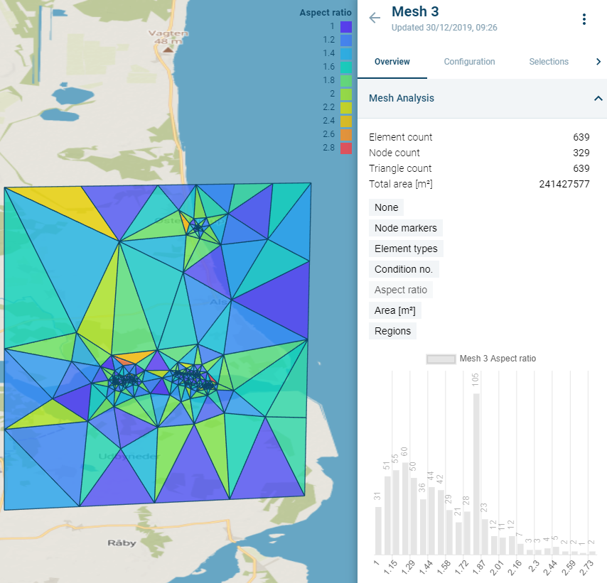
Figure 3‑28 Expanded Mesh Analysis with Aspect ratio clicked open.
Mesh information corresponds to nodal groups (Node markers) and elemental groups (Regions, Types), as well as geometric and quality information (elemental areas, quality metrics).
It is possible to improve the mesh by using Mesh post-operations (automated improvements over bigger areas) and through Queries (finding individual points and editing them).
Mesh post-operations
The Mesh Builder currently provides the option to apply post-operations to the entire mesh object or on a subset of its elements, which can be selected through a query mechanism.
To select an operation, click the ![]() menu to the right of the mesh name, then select
menu to the right of the mesh name, then select ![]() .
.
The panel shows the Operations tab, with a dropdown that enables the selection of the desired operation (see Figure 3‑29).
Note: When applying an operation to a mesh, a copy is made to which the operation is applied. This copy does not immediately become visible in the map.
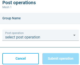
Figure 3‑29 Operations tab in the Mesh Object.
The list of currently available post-operations:
- Assign node markers This operation assigns a node marker value to mesh nodes selected using the query mechanism.
- Delete elements
Deletes the selected subset of elements, leaving holes. An invert switch enables retaining the selected elements and deleting the others. - Extend mesh
After the selection of a polygon in the Extension item ID field, this operation attempts to create a new mesh from the original mesh and the selected polygon, leaving the selected mesh as much untouched as possible.
The Snap tolerance parameter can be used to make gaps disappear between the original mesh and the new addition. The Element buffer level determines how many elements deep the original mesh can be changed by the algorithm (1 meaning the first layer of elements can be altered i.e. the area where the extension touches the mesh).
Note: when going from very coarse to very fine elements, the Element buffer level can help smooth the mesh elements – of course at the cost of changing more of the original mesh. - Merge mesh This operation is used to merge two adjoining meshes. The element buffer level parameter creates a buffer around adjacent elements that limits construction of small elements in gaps between the meshes.
- Quad-dominant
Attempts to merge adjacent triangles to create quadrangles. This operation generally creates a mixed-element mesh in which the proportion of quadrangles is bigger than the proportion of triangles. It can be viewed as a coarsening operation that minimizes the negative impact on simulation engine’s stability that is generally induced by coarsening operations. This minimization of potential coarsening damage relies on the fact that quadrangles are numerically superior to triangles because they allow gradients (referring to the property gradient approximation inherent in PDE solving numerical methods) to vary over the element while triangles only support constant gradients. - Reduce node-elements
This operation reduces the number of nodes connected to more than seven other nodes. It’s possible to increase the number of iterations to obtain better results for complex meshes. - Refine
This method will split the targeted elements to increase mesh density. Each quadrangle will convert into 4 quadrangles and each triangle will convert into 3 triangles. - Local remesh
_This operation will remesh only the elements determined by the query – leaving the rest of the mesh intact.
With the _Incude add-in slider it is possible to determine a Geometry that should be included, for example to allow houses as holes (these will need to be imported or drawn as a Geometry beforehand and then marked as holes).
The Element buffer level field determines determines how many elements deep the original mesh can be changed by the algorithm (1 meaning the first layer of elements can be altered i.e. the area where the queried selection touches the mesh).
Note: it is possible to use a Geometry as a selected area by selecting Geometries as the query location and then picking the desired geometry for the location in the dropdown. This Geometry needs to be created beforehand. - Smooth
Applies a Laplacian smoothing to selected element nodes to improve mesh quality. - Derive geometry
This operation creates a geometry from selected features of the mesh.
After the first dropdown selection is made, a second dropdown appears, allowing for specification of where to apply the operation. If it’s not possible to define the area using one of the query criteria, it is possible to create a Selection (see 3.8.2 Selections).
In summary, the workflow is:
- Select the desired post operation.
- Select the desired mesh elements.
- Click Submit.
Note: remeshing the Mesh Object with the Generate button from the mesh menu will remove post-operations applied to it and generate the mesh from the chosen Mesh Configuration only.
Mesh editing
It’s possible to use mesh editing to move, add, and delete mesh nodes.
Mesh editing is initiated by clicking on ![]() next to the mesh name in the right-hand panel and then selecting, “Edit Mesh Nodes”. This opens the Edit mesh nodes pane on the right-hand side of the application. The Edit mesh nodes pane includes four tabs:
next to the mesh name in the right-hand panel and then selecting, “Edit Mesh Nodes”. This opens the Edit mesh nodes pane on the right-hand side of the application. The Edit mesh nodes pane includes four tabs:
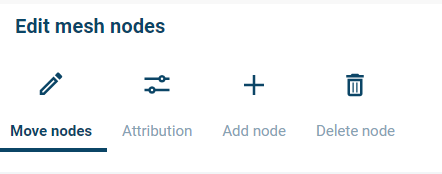
Figure 3‑12 Edit mesh nodes pane: Move nodes, Attribution, Add node, and Delete node tabs
- Move nodes: On the Move nodes tab, it’s possible move, add, or delete nodes in a mesh. To begin, a node must be selected. The cursor is then used to move the node to a new location.
- Attribution: On the Attribution tab, it’s possible to edit node values like node numbers and elevations. Attributes are edited one at a time after selecting a node.
- Add node: On the Add node tab, it’s possible to add a node to a mesh. Click anywhere within the mesh to add a node. New triangular elements will be created around the new node, connecting it to the surrounding nodes.
- Delete node: On the Delete node tab, nodes can be selected for deletion. Deleting a node will remove the adjoining elements from the mesh, creating a hole.
If you would like to save edits during a session, click the “Apply changes” button. Previously applied changes can be undone by clicking on the “Undo” button. Once you are done editing, click on the “Submit” button to finalize the changes.
Mesh selections
Selections are areas of the mesh with a specific meaning to the user. They can, for example, be areas where the mesh should be finer or where elements need to be removed. They can be used as input values in the Mesh post-operations.
They can be found from the main Workspace page when clicking the ![]() button behind the mesh object name and then clicking the tab Selections.
button behind the mesh object name and then clicking the tab Selections.
The tab gives an overview of existing Selections and allows the user to draw a new selection.
Click:  .
.
Draw the desired area on top of the mesh on the left by clicking with the left mouse button at a starting point, then clicking once for each desired area point and then double click to finish drawing. The result should be highlighted like so:
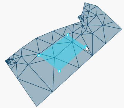
Figure 3‑30 Selection on top of a mesh
A name can be specified for the selection, which will show up in dropdown where it can be used. If no name is given, the default name Selection [auto-number] will be applied.
Click Create to add the selection.
It will then be available in Post operations and Queries in the dropdown with desired mesh elements under Selections:
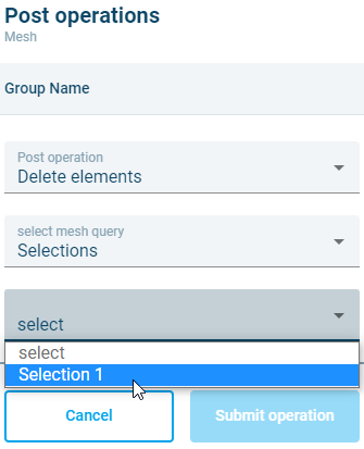
Figure 3‑31 A selection used in Mesh Post-Operations
Queries
The queries can be used to quickly visualise elements of a mesh or to find specific elements (and edit them if need be).
They can be found from the main Workspace page when clicking the ![]() button behind the mesh object name; behind the tab Selections is an option to scroll further right. Click on the arrow pointing right:
button behind the mesh object name; behind the tab Selections is an option to scroll further right. Click on the arrow pointing right:
![]()
The tab Query is revealed.
Click on the tab.
A panel with a dropdown appears, allowing for the selection of the desired query criteria.
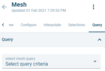
Figure 3‑32 The Query panel
Click on the desired query.
A table appears below the selected query. In some cases it is possible to select a range on top of it, in case the default isn’t specific enough. The table shows a top 10 of elements based on the query.
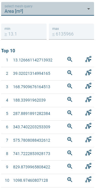
Figure 3‑33 Overview of smallest elements in the mesh
It is possible to zoom to the mesh element in the table by clicking ![]() .
.
In order to change a mesh element:
Click![]() and click with the left mouse button on a node on the map. The node and its connecting nodes will light up.
and click with the left mouse button on a node on the map. The node and its connecting nodes will light up.
Drag the node to desired position, making sure not to cross the highlighted boundaries.
Click  to put the node in its new position. The mesh will be redrawn.
Note: remeshing the Mesh Object will remove changes applied to it and generate the mesh from the chosen Mesh Configuration only.