Defining a new Workspace
Once you have clicked the button to create a new workspace (see 3.1), a new panel will open on the right side of the screen (see Figure 3.6):
-
Project selection
Your selected project is preselected here. If you choose to change it, the workspace will be created in the project you change it to. -
Workspace name and description (optional)
You are free to name your workspaces as desired, and an optional description can be added. If name is left open, the name will be Untitled. -
Data from folder
Data cannot be uploaded directly to the Mesh Builder. Instead, data must be uploaded to MIKE Cloud Admin and then copied to the Mesh Builder. Tick the checkboxes for the data you want to use for the mesh you are about to create. Will only appear if the selected projects holds relevant data in the Data Admin application. Also, if no ticks are set, no data is put into the workspace (this can be changed later).
Note: see below for information on restrictions regarding imported data. -
Data type declarations:
Some dataset types need user definition of their content:- The geometry type should be recognized automatically, provided the source data is a standard shapefile. Items with this type will be used as Geometries to set up the basic shape of the mesh.
- The variable type will not be automatically recognized. Items marked as such can be used as for interpolation.
- The mesh type should automatically be recognized, provided it is in Kitware’s VTU format. These items will enter the MB as previously generated meshes.
-
Projection system The dark EPSG code above the search option is the projection system that will be used to create the workspace. The default is EPSG:4326 WGS 84.
The dropdown/search bar underneath it will determine what the projection will be for your workspace. It allows typing of name and EPSG codes and will show the results. Below the dropdown recently used projection systems will be shown, based on recently used workspaces; clicking any will change the projection system for the Workspace to be created to the selected option.
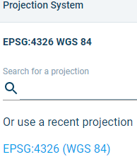
Figure 3‑5 Projection selector and recently used projection underneath
1. If the projection system is different from the one(s) in the selected Data from project (point 3 above), an attempt will be made to convert the selected files to the projection system picked here; however this is not guaranteed to work under all circumstances.
- Note: It is currently not possible to change the projection system after the workspace has been created.

Figure 3‑6 The Workspace creation window and its related user-actions.
Click the Create workspace button once you are done.
Upon Workspace creation success, you enter the Workspace page.
Supported file formats
Not all file formats are (fully) supported yet. The current version only supports the following data formats:
- Geometries: ESRI shapefiles (with standard association: *.shp),
- MIKE internal formats: *.dfs0, *.dfs1, *.dfs2, *.mdf,
- Raster variables: ESRI ASCII Grid format (*.asc),
- Meshes: Kitware VTU (*.vtu), DHI MIKE Zero (*.mesh),
- Other: *.tif, *.xyz, *.vti
This list will grow in time.
Free-to-public data extraction
The Mesh Builder supports access to free-to-public data providers. The amount of data available differs per region and is not subject to screening by DHI.
A project and workspace are required for the extraction. Once those are created and no other data is present, MB will offer the option to extract data:
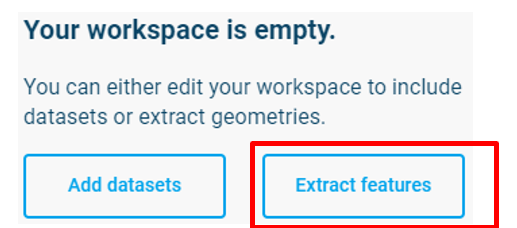
Figure 3‑7 Add datasets or extract features in an empty Workspace
If you want to use the data extraction in a project that already has some data in it, click the ![]() tool on the left menu while no other items are selected on the right.
tool on the left menu while no other items are selected on the right.
Zoom to the area of the map that you wish to extract; or – if you have a polygon representing the area of interest – select that from the geometries on the right (this allows you to skip the next two steps, continue under the note, below).
- Click with the active tool to select your first point, then proceed to draw lines and click until you have the area you want to extract.
- Double click to close the selected area. A closed polygon should appear.
Note: for more options such as deleting a point, look under the keyboard shortcuts (![]() in the top right.
in the top right.
Once the area is selected, select a data provider that you would like to extract from the panel on the right.
The following data providers are available:
-
OpenStreetMap: The OpenStreetMap provider enables retrieval of GIS vector representations of land surface features, including elements of the natural and built environments. More information about the data can be found here. The following data sets are available for extraction:
- Coastline
- Road
- Building
- River bed
- River path
- Lake
- Landcover -
NOAA: The NOAA data provider enables retrieval of GIS vector representations of coastlines. High-, medium-, and low-resolution data sets are available. More information about the data can be found at https://shoreline.noaa.gov/.
-
GEBCO: The GEBCO data provider enables retrieval of raster bathymetry data. The 2024, 2023. 2022, 2021, and 2020 data sets are available. The 2021, 2023, and 2024 data set include a ‘sub-ice’ option that uses land surface elevations for areas covered by permanent ice. More information about the data can be found at https://www.gebco.net/data_and_products/gridded_bathymetry_data/.
Once the area and type are correct, click Extract. At this point, changes can be made before a geometry is created, so Simplify and Dissolve operations can be used on the extracted data, and drawing tools on the left can be used to change and add points to the extraction.
When you are satisfied with the extracted item to be added to the Geometries, click Create.
The extraction may take a while, depending on the area and the amount of data, and will then be added as a geometry.
This extraction can be done multiple times in a single area to get multiple types of data.
Projection systems
The Cloud platform currently supports over 9000 different projection systems. There are currently 28 projection systems that are currently not supported (see Appendix: Non-supported projection systems). Please specify the projection system of the file you are uploading in Data Admin, as it allows MB to correctly use this information.
The projection (EPSG) code of the workspace is reported in the bottom bar of the screen once you enter the Workspace (see Figure 3.8). For information on how to set the projection system at workspace creation, see Section 3.2.