Geometries
Geometries
Geometries are analogous to GIS vector data. Geometries can consist of polygons, polylines, or points.
Creating a geometry
If you want to draw your own geometry instead of uploading a file or extracting data, go to the Workspace and click on the tool in the left bar:
![]()
This will open five options:
![]()
- Draw rectangle
- Draw circle
- Draw polygon
- Draw polyline
- Draw point
Clicking on rectangle, circle, or polygon will open the geometry drawing pane on the right-hand side of the application. The selected polygon type will be selected in the right hand pane.
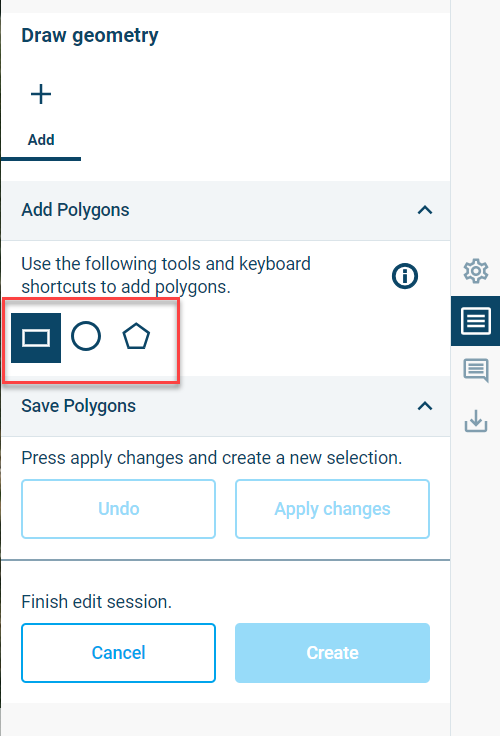
Figure 3‑9 Geometry drawing tab with polygon type selection outlined in red
You can then begin drawing the selected polygon type or change the polygon type. It’s possible to add two or more polygons to a geometry. If you would like to save your new polygons during a drawing session, click the “Apply changes” button. Previously applied changes can be undone by clicking on the “Undo” button. Once you are satisfied with the geometry, click on the “Create” button to create the new geometry.
Circles are drawn from the center.
A polygon is completed by double clicking or pressing the space bar at the end of them.
It is possible to freehand a polygon or polyline by pressing the CTRL key while moving the mouse.
Clicking on the polyline tool in the left-hand bar will open the polyline drawing pane. The polyline tab is like the polygon tab. It’s possible to include two or more polylines in a geometry.
Clicking on the point tool in the left-hand bar will open the point geometry drawing pane. The point tab also function in the same way as the polygon drawing tab.
It is possible to rename a geometry after creating it, by clicking the menu item ![]() behind its name from the main Workspace page and clicking
behind its name from the main Workspace page and clicking ![]() .
.
Click on the name and change it. Click ![]() once you are done. The item will be renamed.
once you are done. The item will be renamed.
We will now go into more detail for this panel, called the Geometries panel.
The Geometries panel
The geometries panel is displayed in Figure 3.9 and can be found on the right side of the screen after clicking the ![]() button for any item under geometry.
button for any item under geometry.
The panel has an action menu to the top right (![]() ) and further consists of multiple tabs (in the example Figure 3.9 this would be Overview and Selections), the option to exclude it from the mesh (considering it a hole), an area called Geometry Analysis and an area called Visualisation Settings.
) and further consists of multiple tabs (in the example Figure 3.9 this would be Overview and Selections), the option to exclude it from the mesh (considering it a hole), an area called Geometry Analysis and an area called Visualisation Settings.
The action menu gives all the available options that can be used for this Geometry.
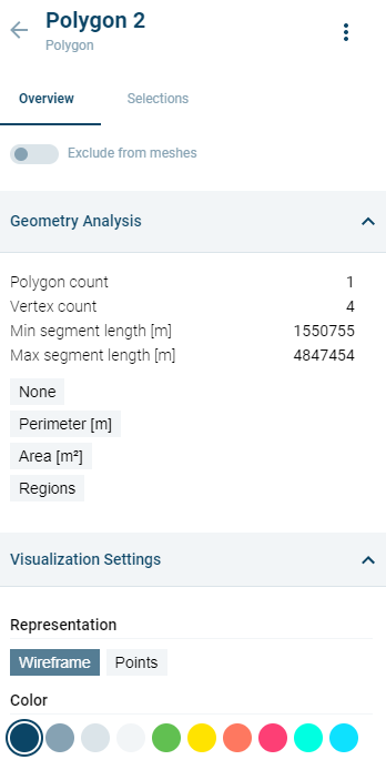
Figure 3‑10 Geometries panel: Plotting of metadata controls and accessible actions.
The Geometry Analysis area enables you to look at certain data more in depth. It shows polygon and vertex count and segment lengths, but also other variables that can be clicked and reviewed (for more info, see 3.7.5).
The Visualisation Settings make it possible to change the appearance of the Geometry in the map area: when clicked, it can change from wireframe to points and can change the colour.
Geometry selections
The Selections tab in the Geometries panel shows spatial selections made for the selected geometry and provides functionality for creating new selections. When creating a mesh using a geometry, selections enable assigning different properties to the selected area, such as finer or coarser meshing. Selections can also be used to specify open boundaries.
Spatial selections can be initiated by clicking on the button, ‘Make a spatial selection’ or by clicking on the Spatial selection icon (![]() ) from the left menu. Once the selection is initiated, a selection can be made be drawing by hand or by selecting another geometry. A selection can be made inside a polygon geometry without intersecting any line segments
of the geometry.options while in this panel.
) from the left menu. Once the selection is initiated, a selection can be made be drawing by hand or by selecting another geometry. A selection can be made inside a polygon geometry without intersecting any line segments
of the geometry.options while in this panel.
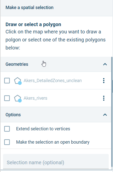
Figure 3‑11 Making a spatial selection
The options, ‘Extend selection to vertices’ and ‘Make the selection an open boundary’ can be used to create open boundaries when using a geometry in a meshing operation. ‘Extend selection to vertices will extend the portion of any line segment included in a selection to the next vertex outside the selection area. ‘Make the selection an open boundary’ will, during meshing, assign open boundary node numbering to mesh nodes located on segments within the selection area.
Duplication of geometries
Geometries and meshes can be duplicated. From the main Workspace page, go to the item to be duplicated and click the menu item ![]() behind its name.
behind its name.
Click  .
.
The duplicated item is added.
Replacing a geometry
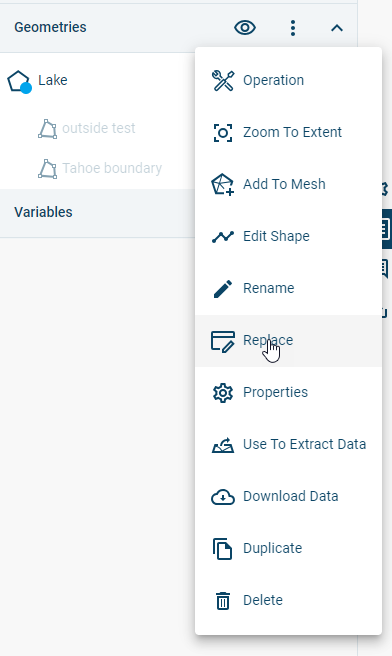
A geometry can be replaced with another geometry from Cloud Admin without changing the name or other properties of the geometry. In this way, geometries can be ‘updated’ from outside the Mesh Builder. To replace a geometry, click on the three-dot icon to the right of the geometry name and select “Replace”.
 .
.
Geometry operations
Operations change the structure of geometries. Operations can be accessed as follows:
-
from the Workspace page on the right panel at the geometry level, by pressing
 and then picking
  . This will lead to a selection menu where the geometries that the operation should be applied to can be selected.
 -
from inside the geometry, use the
menu on the top right, then choose.
For some geometry operations, it’s possible to limit the operation to a subset of the selected geometry using the Select Attribute field. The following options may be available, depending on the selected operation:
- All: Entire geometry
- Id: Selected geometry IDs. Only a range can be selected.
- Area: User-specified range of polygon areas.
- Perimeter: User-specified range of polygon perimeters.
- Elevation: User-specified range of elevation attribute values
- Selections: If a selection has been defined on the geometry, it’s possible to limit the operation to the selected areas.
- Geometries: It’s also possible to use another geometry to define the spatial extent of the geometry operation.
If a geometry has other attributes, it’s also possible to limit an operation to range of values for one of the other attributes.
By default, an operation will create a new geometry, preserving the original. However, it’s possible to overwrite the original by disabling the switch, “Create geometry copy”.
The following operations are available:
Aggregate
This operation will combine existing polygons based on the indicated distance between them and how different the new shape is allowed to be.
The operation has three parameters that can be used to define the outcome:
- Distance between original polygons in meters indicates how closely together polygons need to be in order to be aggregated. Default is 100m
- Polygon outline fidelity in meters determines how closely the aggregated polygon will follow the outlines of the original polygons. Default is 40m.
- Percentage change of polygon outline in % determines how much the outline of a polygon is allowed to change in the operation. Default is 0%.
Buffer
This operation creates a new polygon that is bigger or smaller than the selected polygon.
A value in meters needs to be entered for the operation to work. A negative entry (i.e. -10) will cause the polygon to shrink. Default is 100m.
Clip
This operation enables you to create new geometries from existing polygons by selecting the ‘subject’ you want to have a part of and then defining a ‘clipper’ polygon by which the subject is then clipped. The selected operation determines the behaviour:
- Intersection: clips the selected polygon where it is intersected by the clipper polygon. A new geometry is created from the area where clipper and subject intersecting areas.
- Difference: clips the selected polygon where it does not overlap the clipper polygon. A new geometry is created from the areas where there is no overlap with the subject.
DensifyThis operation adds more vertices to the geometry by splitting its segments. A value in meters needs to be entered that determines where the split will occur. Example: 100m will split segments every 100m of their current length, whereas 30m will split them every 30m of the length, creating more vertices. Default is 100m.
By default, this operation will keep the original geometry points. It is possible to change this by clicking the switch in front of Keep geometry points (the dot should be on the left to turn this off).

Extract by attribute This operation creates a new geometry as a subset of the geometry that the operation is performed on. Select an attribute (i.e. Region, ID or Length) and define the minimum and maximum values to specify what to include in the new geometry.
Polygonize
This operation will try to turn multiple polylines into a single polygon (only available for geometries of type Polyline).
Simplify
This operation reduces the number of vertices of the geometry. Two options are available.
- A Douglas-Peucker algorithm, which requires setting a tolerance in meters.
- An option that removes all segments smaller than a user-specified distance.
Simplify buildings This operation reduces the number of vertices of the geometry and is targeted at simplifying shapefiles depicting building footprints in an urban setting. The logic is based on an algorithm proposed by Gwanyong Park, Changmin Kim, Minhyung Lee and Changho Choi in the following paper:
https://www.mdpi.com/2076-3417/10/16/5425
The algorithm removes “insignificant” edges by checking the perpendicular distance between the centres of each edge pair and angle between edge normals. The following parameters are used:
- Simplification distance (meters): Minimum perpendicular distance between edges. Default is 5 meters.
- Simplification angle (degrees): Minimum angle between edge normals. Default is 30 degrees.
If the distance or angle between edge pairs is less than the simplification distance or simplification angle, then the shorter of each pair is removed and a new building perimeter is constructed from the remaining edges.
The following additional parameters are available.
- Snap distance (meters): The operation will attempt to connect buildings separated by less than this distance. Default is 0.5 meters.
- Spike angle (meter): The operation will attempt to remove ‘spikes’ in building edges with an angle less than this value. Default is 30 degrees.
![(images/Spike_removal.png)
- Remove holes: If enabled, this switch will remove polygons that are entirely enclosed by other polygons. The switch can be used to remove courtyards and other enclosed areas. Default is on.
Smooth
This operation smooths the geometry path. A value must be entered for the number of control points to be added to each input vertex to create a smooth curve. Default is 5.
If the option of keeping the geometry points intact is chosen, additional control points are interpolated by the Catmull-Rom algorithm. If not, then the points are approximated by Chaikin’s algorithm.
Snap
This operation snaps a geometry to a second geometry (for example, a building geometry to a road geometry, or the reverse). This can help reduce generation of small mesh elements with small angles when two parallel lines are very close together.
The snapping operation moves vertices of the main geometry to the same location as the vertices of the “snap to” geometry (if the vertices are separated by a distance less than the snap tolerance). Because snapping operates on vertices, it may be useful to run a densify operation on both the main and “snap to” geometries before snapping.
Split
This operation splits an existing geometry into two or more geometries. A splitting polyline must also be specified.
Union
This operation enables the creation of one new polygon from several existing polygons.
Split by attribute
This operation enables the splitting of a geometry by one of its properties. Currently the limit of geometries generated from this is set at 25, so if the operation would generate more geometries it will fail.
Editing geometries
Geometries can be edited, either by moving existing vertices; adding vertices; deleting vertices; adding new polygons, lines, or points to existing geometries; or with editing operations.
Geometry editing is initiated by clicking on ![]() next to the Geometry name in the right-hand panel and then selecting, “Edit Shape”. This opens the Edit Geometry pane on the right-hand side of the application. The Edit Geometry pane includes four tabs:
next to the Geometry name in the right-hand panel and then selecting, “Edit Shape”. This opens the Edit Geometry pane on the right-hand side of the application. The Edit Geometry pane includes four tabs:
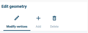
Figure 3‑12 Edit Geometry pane: Modify vertices, Add, and Delete tabs
- Modify vertices: On the Modify vertices tab, it’s possible to add, move, or delete vertices from a polygon or polyline. It’s also possible to move points in a point geometry. To begin, one or more polygons, polylines, or points must be selected. Vertices can be added to the selected polygon or polyline by clicking anywhere between two vertices. Vertices can be moved by clicking and dragging. Vertices can be deleted by clicking while holding down the Alt key.
- Adding new polygons, polylines, or points: On the Add tab, it’s possible to add new polygons, polylines, or points to an existing Geometry. The functionality is like creating a new geometry (3.4.1). New polygons, lines, and points can be added to a geometry by clicking anywhere besides the existing geometry. It’s not possible to mix different geometry types in the same geometry (in other words, polygons cannot be mixed with polylines).
- Deleting polygons, polylines, or points: Polygons, polylines, and points can be deleted by clicking on the Delete tab and selecting points for deletion.
If you would like to save edits during a session, click the “Apply changes” button. Previously applied changes can be undone by clicking on the “Undo” button. Once you are done editing, click on the “Submit” button to finalize the changes.