Generating meshes
Generating meshes
Once the geometries and variables are set up, it is possible to create a mesh.
From the main workspace page, click the button on the top of the panel New Mesh:
The first step is to determine which geometries should be added to the mesh, as not all geometries in the workspace might be relevant. The right panel shows an overview of the available geometries in the current workspace.
Tick the boxes of the geometry items that you want to add:
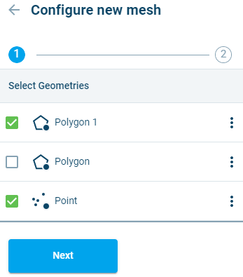
Figure 3‑18 Selecting input items for further configuration and mesh object creation.
As a visual aid, the selected items will turn a different colour in the map area.
Click  once all the geometries are selected.
Configuring basic mesh parameters
The panel switches to the Configure new mesh panel. Within this panel, it is possible to make changes to some general mesh settings, as well as settings for each geometry.
All algorithms in the MB application performing constrained Delaunay quality triangulations are based on minimization and maximization principles regarding triangles shape and size. The algorithms attempt to maximize the minimum angle between two edges of a triangle ($\alphamin), while making sure that the smallest angle in the triangulation is least as large as the smallest angle in any other mesh triangle. It also minimizes the triangles edge-length (dmax).
The general mesh settings are:
- Min angle; this is the minimum dihedral angle - $\alphamin , a limit on the lower bound of the angle formed by two adjacent edges of a triangle in the generated mesh. The default value is 26 degrees.
Note: This control parameter has the highest effect on mesh quality. Values bigger than 30 degrees are known to likely generate mesh failure and should generally not be used. - Snap tolerance: this parameter specifies a distance in meters below which vertices of the geometries to be meshed are snapped to the same location
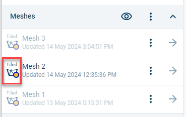
When generating a mesh, it’s possible to enable tiling, which makes it easier to view large meshes. The tiling functionality splits the mesh into rectangular tiles consisting of 50,000 elements; this makes it easier to zoom in and out of the mesh because only a subset of the mesh needs to be retrieved for viewing. Tiling can be activated for meshes with more than 2.5 million elements. Tiling is activated by disabling the switch, “Suppress Tiling”, in the mesh configuration.
After a mesh has been generated using tiling, an icon informs the user that the mesh is tiled.
If the number of elements in field of view for a tiled mesh exceeds 50,000, then a coarse dummy mesh is shown. Once the user zooms to a level where the number of elements is less than 50,000, then the actual elements are shown.
The mesh size limit is 25 million elements. Tiling is activated automatically when importing meshes with more than 2.5 million elements.
To configure meshing parameters for a geometry, click the  button next to it. Five meshing options are available: Triangulate (default value), Rectangular (mostly used for offshore), Channel (mostly used for channels), Radial (for meshing a radius around a point), or Coastline (used for creating triagular meshes adjacent to coastlines). Additional specifications are made depending on the choice of mesh operation.
Triangulate
The triangular mesher is available for all geometry types.
- Size criteria: Users have a choice of two criteria for specifying the minimum size of mesh elements: area or edge length.
- Maximum element face length (m) or area (m2): This limit is applied throughout the meshing area.
- Element length (m) or maximum area (m2) at mesh border: This constraint is applied along polygon borders and/or polylines.
- Use only vertices: If this switch is turned on, only geometry vertices will be inserted into the mesh, while line segments will be ignored.
- Enable gradual size: If a different sizing criterion is applied at the mesh border, this switch will enable a gradual transition.
- Use background density function: This switch enables use of a variable to control the density of mesh elements. More information is available in Appendix A. This switch activates the following input parameters:
- Number of points (default 10.000): This is the number of mesh nodes to be generated by the density function.
- Buffer size: This parameter excludes a buffer adjacent to the geometry from the densification operation.
- Select a variable or no variable: This field enables selection of variable to control the density of mesh elements. The density of elements will be increased in areas with larger values. It’s also possible to use the density function without a variable. If a variable is selected, two additional switches can be applied:
- Apply gradient: This switch uses a gradient instead of actual values to drive densification, with higher density applied in areas with larger gradients.
- Invert the density function: This option will increase the mesh density in areas where variable values are lower (or areas with small gradients if ‘apply gradient’ is selected).
- Selections: If a selection has been defined on the geometry, it’s possible to apply different size limits to the area of the geometry within the selection. In addition, it’s possible to designate the selected part of the geometry boundary as an open boundary for the mesh.
Rectangular
The rectangular mesher is available for polygon geometries only.
- Element width: This parameter determines the width of the generated rectangles.
- Element height: This parameter determines the height of the generated rectangles.
- Orientation angle: This parameter determines the angle at which the rectangles are generated
- Border policy: This determines how to handle the generation of elements at borders. There are three options:
- Overlap: Rectangles will be created and overlap the border where they are too big to fit.
- Leave gap: Rectangles will be created until they cannot fully fit, the remaining area of the selected domain will be left empty.
- Fill with triangles: Rectangles will be created until they cannot fully fit, and in the remaining area triangles will be generated. If this option is selected, a width must be specified for the triangular buffer, and size criteria must also be specified (see Triangulate for details).
- Selections: If a selection has been defined on the geometry, it’s possible to apply different size limits to the area of the geometry within the selection.
Channel
The channel mesher is available for polygon and polyline geometries.
- Resolution method: Two options are available for specifying the size of the mesh: Number of elements and Size of elements. When choosing Number of Elements, the user specifies the number of rows and columns in the mesh. When choosing Size of Elements, the inputs required are:
- Optimal length flow direction (default: 40m)
- Optimal length transverse direction (default: 10m)
A Buffer width can be specified when using the Channel mesher with a polyline geometry.
Radial
The radial mesher is available for point geometries only.
- Radius: The radius the generated mesh should have.
- Radius of hole: A hole can be placed at the center of mesh by giving this parameter a value greater than zero.
- Fill hole: This switch will fill a center hole with triangular elements.
- Element length at mesh border: This enables the user to specify the element length at the outermost part of the mesh.
- Slice angle: This parameter enables the user to create a radial mesh for a portion of a circle.
- Orientation angle. This parameter specifies the starting angle for a mesh. The default is zero degrees (12 o’clock)
- Element type: Users can choose between four- and three-sided elements.
Coastline
-
The coastline mesher is available for polyline geometries only.
-
Boundary: The user should select a polygon to define the open boundaries of the coastal mesh..
- Size criteria: Users have a choice of two criteria for specifying the minimum size of mesh elements: area or edge length.
- Maximum element face length (m) or area (m2): This limit is applied throughout the meshing area.
- Element length (m) or maximum area (m2) at open boundary: This constraint is applied along the open boundaries of the mesh.
- Element length (m) or maximum area (m2) at coastline: This constraint is applied along the coastline.
- Buffer: This parameter maintains the coastline element size specification for a user-specified distance from the coastline.
- Area of interest: This enables using a second polygon to define an area of interest within the domain where a different maximum size criterion can be applied.
- Flip land: The coastline mesher will automatically locate the mesh in the part of the bisected boundary polygon with the largest area. This switch enables the user to select the reverse.
- Enable gradual size: If a different sizing criterion is applied at a mesh border, this switch will enable a gradual transition.
- Use background density function: This switch enables use of a variable to control the density of mesh elements. More information is available in Appendix A. This switch activates the following input parameters:
- Number of points (default 10.000): This is the number of mesh nodes to be generated by the density function.
- Buffer size: This parameter excludes a buffer adjacent to the geometry from the densification operation.
- Select a variable or no variable: This field enables selection of variable to control the density of mesh elements. The density of elements will be increased in areas with larger values. It’s also possible to use the density function without a variable. If a variable is selected, two additional switches can be applied:
- Apply gradient: This switch uses a gradient instead of actual values to drive densification, with higher density applied in areas with larger gradients.
- Invert the density function: This option will increase the mesh density in areas where variable values are lower (or areas with small gradients if ‘apply gradient’ is selected).
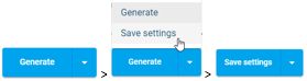
Once the parameterization is finished, there are two options: save settings - this option will save the current work, but not generate a mesh yet, and Generate - this option will save the current work and immediately start generating a mesh. Per default MB will suggest to Generate, but if you would rather save your settings this can be done by clicking the arrow on the Generate button and then selecting the other option. The button will then switch to the Save settings option and once clicked will perform only a save but not generate a new mesh yet:
Both options will generate a new object, a Mesh Object. This will appear under the header Meshes in the main Workspace page.
A Mesh Object can be duplicated, deleted and saved, as well as structurally modified by post-mesh operation methods (see 3.8.1), or updated by changing input data and/or control parameters.
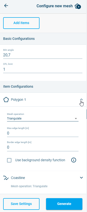
Figure 3‑19 Selecting input configuration parameters.
Adding items to a Mesh Object
In order to add any new variable and/or geometry to a Mesh Object, there are two ways to get to the same point:
- The fist option is from the Main Workspace page.
Go to the variable or geometry and click on the menu button behind the name, then click
  .
.
An overview will appear with available meshes. Boxes will be ticked and greyed out for meshes that already contain the object.
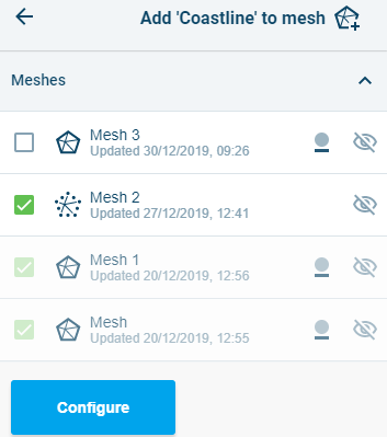
Figure 3‑20 Selection of meshes to add the item to.
Tick the boxes for the meshes that you want to add your data to, then click Configure.
Note: adding items will cause Mesh Objects to be remeshed.
- Alternatively, enter the mesh object (from the main Workspace page, click on the
 button behind the mesh under the Meshes header).
Click on tab Configuration at the top of the page, then click the Edit configuration button at the bottom and then click Add items at the top.
This will show an overview of available objects. Items that are already a part of the Mesh Object will be ticked and greyed out.

Figure 3‑21 Selection of items to add to the mesh.
- Tick the boxes for the items that you want to add to the mesh.
Note: adding items will cause Mesh Objects to be remeshed.
Removing items from a Mesh Object
Any variable and/or geometry can be removed from an existing Mesh Object.
Click on the ![]() button behind the mesh under the Meshes header in the main Workspace page to go into that mesh.
button behind the mesh under the Meshes header in the main Workspace page to go into that mesh.
You will enter the Overview tab.
Scroll to the bottom to find the header Mesh items.
Each of these items has a ![]() button behind it. Using it will remove the item from the mesh and cause the mesh object to be refreshed with the new situation.
button behind it. Using it will remove the item from the mesh and cause the mesh object to be refreshed with the new situation.
Interpolating a mesh
Once the mesh has been generated and looks as desired, it can be interpolated if there are Variables available for interpolation. This can be done from inside the mesh settings by clicking the Interpolate tab:
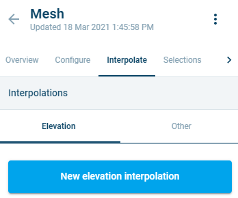
Figure 3‑22 Interpolate tab
If there are no available Variables, the user is prompted to add one or more. You can add Variables by editing the workspace (see 3.3.2) and uploading a file with variables, or by drawing your own (see 3.5).
The user can select between two types of interpolation: Elevation (used for applying height and depth values to the mesh) or Other (any other type of interpolation of values defined by the user. The major differences between the two options are as follows:
| Elevation | Other |
|---|---|
| Interpolates to nodes | Interpolates to nodes or elements (choice) |
| Lets user apply a CFL operation using CFL limit and sea level | No CFL operation |
| Results come under ‘Elevation’ variable in the overview | Results come under chosen name by user |
Click the tab for the type of interpolation that is desired, then click:
Select the file(s) that should be used in the interpolation by ticking the box(es) in front of them.
Note: MB does not support multiple elevation variables in one location. Instead, a prioritization scheme is used to determine which variable should be used. See below for more information.
Click:
For an Elevation interpolation, there will be the option to Apply a CFL operation. When the slider is clicked two more fields will appear:
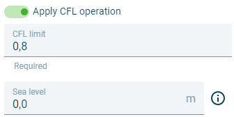
Figure 3‑23 Slider for CFL operation active under Elevation interpolation type
Based on the CFL limit (default 0,8) and the Sea level (0m), a Minimum Estimated Timestep is calculated and added to the Mesh Overview after the Interpolation is finished.
For the Other interpolation type, two basic settings need to be filled out:
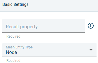
Figure 3‑24 Basic settings for the Other interpolation type
The Result property is the name the property will have once it is interpolated, and by which it can be found in the Mesh Overview. The name can be chosen freely.
The Mesh Entity Type determines whether the values are interpolated to the nodes or to the elements instead.
For both types of interpolations the variable settings are displayed below:
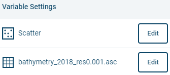
Figure 3‑25 Variable settings in interpolation
Click on the Edit button.
This will open up the settings:
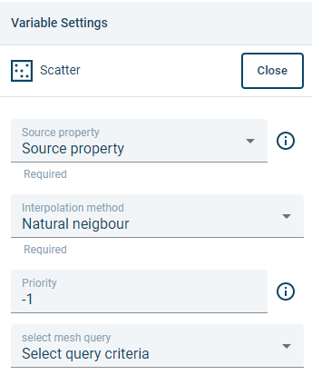
Figure 3‑26 Variable settings in edit mode
There are four settings:
-
Source property: The property that is used to determine the values. Make sure the correct property is selected.
-
Interpolation method: There are three interpolation methods:
- Natural neighbour: The values are based on Voronoi tessellation (default).
- Inverse distance weighting: The values are calculated with a weighted average of the values available at the known points.
-
Linear: Values are determined by a method of curve fitting using linear polynomials.
-
Priority: If an interpolation uses two or more variables, then the priority setting is used to determine which variable to use in case of overlap. The lowest number establishes the highest priority.
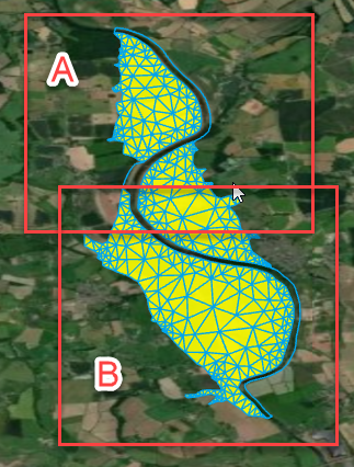
Figure 3‑27 Example of variable prioritization. If A has higher priority, then A will be used to interpolate the mesh in the area where A and B overlap.
- Select query criteria: The interpolation can be applied to parts of the mesh, determined by the query criteria. If, for example, the interpolation should only be applied on a certain region or user defined selection area (make the selection on the Geometry), it is possible to select it here.
Note: when using mixed scatter and raster datasets, they cannot overlap. Selections or Regions need to be defined to make sure the interpolation can happen correctly.
Once this is done for the variables that should be interpolated, click:

The interpolation is done in the background. Once it is done, it is possible to view it by clicking the ![]() (for the Elevation type), Minimal Time Step or named option (for the Other type_)_ in the Mesh Analysis, or to go to the 3D mode and view the whole there.
(for the Elevation type), Minimal Time Step or named option (for the Other type_)_ in the Mesh Analysis, or to go to the 3D mode and view the whole there.
Exclude items from mesh (holes)
Depending on the application domain, holes can have different representations. They either correspond to a physical reality or a conceptual definition. A hole in a mesh is an internal area where elements are missing, thus defining an internal border. Frequent use of holes in meshes is found in urban applications involving the presence of buildings and large human-made structures that act as full barrier to surface flows. Islands are often excluded from a marine application mesh using such holes. Inland water bodies such as lakes may also be excluded from the mesh and further handled by means of engine specific boundary conditions.
Polygons with holes can be directly imported from shapefiles. Standard polygons can additionally be assigned (or unassigned) the ‘Hole’ status. This is a typical polygon characteristic that Delaunay meshers can account for during the mesh generation which, when successful, delivers back a mesh body with corresponding physical holes.
Geometries can be excluded from the mesh from inside the Geometries panel. From the main Workspace page, click the ![]() button behind the name to enter the Geometry. On the Overview tab, there is a switch:
button behind the name to enter the Geometry. On the Overview tab, there is a switch:

When the dot is on the left, it means this item is not excluded from the mesh. Click on it to move the dot to the right, and thereby exclude it from the mesh.
Alternatively, it’s possible to exclude a geometry in the mesh configuration settings.
